Some of the sites for information on the ESP3266 line of processors integrated into PCBs is Elecrow (site may not work), Utmel Electronics and Electronics Hub. This excerpt compares and contrasts the devices. Other modules specifications at Ai-Thinker Technology.
Good source for pin functionality and tutorials at Random Nerd Tutorials.
ESP8266 is a low-cost and high-performance wireless SOC, which provides endless possibilities for integrating WiFi functions into other systems. It can control input and output like Arduino, but the special feature is that it comes with Wi-Fi.
Compared with other Wi-Fi solutions on the market, ESP is the best option for most “Internet of Things” projects! Because it is so cheap that it only costs a few dollars, it can also be integrated into advanced projects. And ESP is also compatible with Arduino IDE. If you have used Arduino before, you will get started quickly using ESP8266.
The ESP-12F and ESP-12E are the same size and have the same pins. The antenna design is the only difference between the two. The updated ESP-12F antenna is said to be better tuned. The ESP12E and ESP12F are nearly identical modules, but the ESP12F is a better variant of the ESP12E with a better antenna design and higher output power.
Capabilities
- Operating Voltage: 3.3V, 5V tolerant
- Maximum current draw per pin: 15 mA
- 2.4 GHz Wi-Fi (802.11 b/g/n support)
- Wireless Network Type:
- Station
- Access Point (SoftAP)
- Station + Access Point (Promiscuous mode)
- Encryption: WEP64 / WEP128 / TKIP / AES
- Network Protocol: IPv4, TCP / UDP / FTP / HTTP
- Single 10-bit SAR ADC channel
- Can read VCC 3.3V supply or ADC input pin
- On-Board FLASH to Hold Program Instructions
- Secure Digital Input/Output Interface (SDIO)
- SD_D0, SD_D1, SD_D2, SD_D3, SD_CLK, SD_CMD
- Capacity: 4 MB
- Secure Digital Input/Output Interface (SDIO)
- All GPIOs support interrupt except GPIO16.
- UART0 Supports 112500 baud maximum: GPIO1 (TX), GPIO3 (RX)
- LED on ESP-12E module connected to GPIO2.
- Four programmable PWM
- Pins: GPIO12, GPIO14, and GPIO15
- Up to 14-bit resolution
Module Pin Capabilities
Below is a list of the individual capabilities of each pin.
| GPIO Pin | NodeMCU Pin | Notes | At BOOT | User I/O Capability |
|---|---|---|---|---|
| 0 | D3 | Pulled HIGH, connected to FLASH button | Connected to FLASH button. Boot fails if pulled low. | 10k H/W PUP, In, Out |
| 1 | TX | Don’t use with serial transmit | High. Boot fails if pulled low. | |
| 2 | D4 | On-module LED | Boot fails if pulled low. | 10k H/W PUP, In, Out |
| 3 | RX | Don’t use with serial receive | High. | |
| 4 | D2 | (I2C SDA) | In, Out | |
| 5 | D1 | (I2C SCL) | In, Out | |
| 6-11 | — | On-module program storage FLASH (pins not usable) | n/a | n/a |
| 12 | D6 | SPI MISO | In, Out | |
| 13 | D7 | SPI MOSI | In, Out | |
| 14 | D5 | SPI SCLK | In, Out | |
| 15 | D8 | SPI CS, Pulled LOW | Boot fails if pulled high. | 10k H/W PUD, In, Out |
| 16 | D0 | Used for wake from deep sleem. No IRQ/I2C/PWM. | High. | Wake, In, Out |
Notes:
- I2C implemented via Software, 100 kHz maximum, pins software selectable. Typical pins in chart above.
- Specific board may have USB V5+ available on external pin. NodeMCU has it available on pin VU and appears to be USB positive voltage after passing through BAT760 Schottky diode (0.55 Vf max).
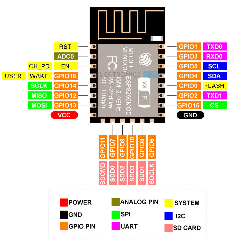
ESP-12E Module
Below is the pinout for the devices from Electronics Hub.

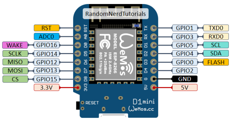
Wemos D1 Mini – ESP-12F Module +Carrier PCB
These parts are attached to many different open source hardware devices and PCBs. This is the pinout of a common one from RandomNerdTutorials – ESP8266 WeMos D1 Mini Pinout. The device has an on-board 5V to 3.3V regulator; but remember, all pins are only 3.3V tolerant.

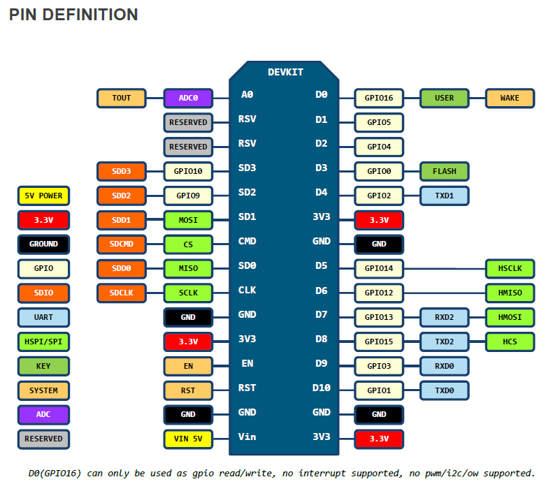
Ideaspark – ESP-12E Module + Larger Carrier PCB
This ESP8266 part contains an ESP-12S module but is treated like an ESP-12E with more exposed pins on the carrier PCB. In the Arduino IDE, you can select the NodeMCU 1.0 (ESP-12E module). The USB-C connector is at the bottom of the Pin Definition diagram below. The Wi-Fi antenna is at the top.
Note: SDD0, SDD1, SDD2, SDD3, SDCLK, SDCMD are used by program FLASH and NOT AVAILABLE FOR USE.

NodeMCU schematics and other information.
Additional Information
The best online source for information on the ESP8266 family and maker help is the Random Nerd website. Check it out. It is the source to determine which pins are available for general use and which are used during the boot sequence and must be used with care (or not at all).
